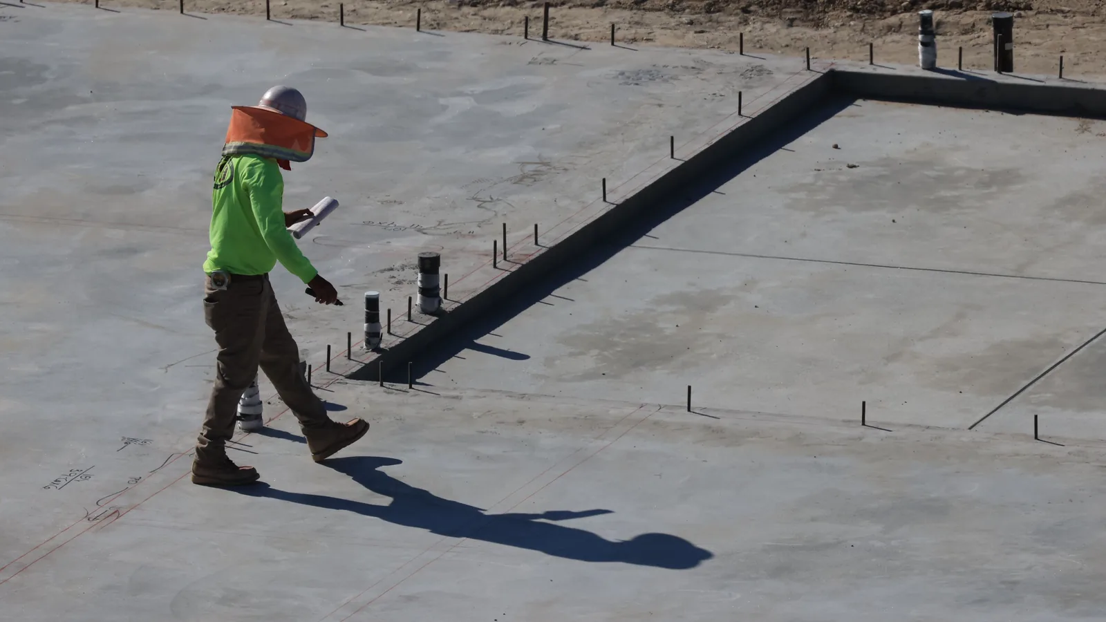


Construction quality depends on more than the experience of the site team. It also depends on the quality of the information provided to them.
A specification may describe the required materials and performance, but it may not explain how different parts of the work connect at a particular location. Verbal instructions may resolve an immediate question, but they may not be communicated consistently across the wider programme.
Clear technical drawings help convert design intent into buildable information.
For retrofit, this is especially important because work must connect with an existing building that may contain irregular construction, previous alterations and restricted access.
Drawings should respond to the existing building
A generic construction detail can provide a useful starting point, but it does not automatically become suitable for every property.
Technical drawings should be informed by the available survey information and should identify where further confirmation is required.
Relevant information may include:
- Existing wall, roof and floor construction
- Window and door positions
- Eaves and verge arrangements
- Rainwater goods
- External services
- Internal fixtures and finishes
- Ventilation equipment
- Structural features
- Existing defects
- Access constraints
Where the existing condition remains uncertain, the drawing should not create false confidence. A survey requirement, opening up location or site verification note may be more appropriate.
Focus on interfaces
Many construction defects occur at interfaces rather than within the main area of a system.
For insulation work, the central area of a wall may be straightforward. Greater attention may be required at windows, doors, floors, roofs, service penetrations and changes in construction.
A useful technical detail should communicate:
- Material position and continuity
- Dimensions where they are important
- Fixing requirements
- Junctions with adjacent work
- Sealing and weathering
- Airtightness requirements
- Fire stopping where relevant
- Ventilation penetrations
- Finishing and protection
- The order in which work should occur
This allows the installer, supervisor and reviewer to understand the intended completed arrangement.
Draw for the intended user
Technical information should be prepared for the people expected to use it.
A drawing intended for installation should not rely on unexplained notation or excessive text. Important dimensions, materials and sequences should be clear. Enlarged details may be required where the main drawing cannot communicate the interface properly.
The site team should be able to answer three questions:
- What am I expected to build?
- How does it connect with the surrounding work?
- What should I do when the actual condition is different?
If these questions cannot be answered, the drawing may be technically correct but operationally ineffective.
Coordinate drawings and specifications
Drawings should not exist separately from the wider design information.
Material references, performance requirements, product information and construction notes should be consistent across the drawing set and specification.
Conflicting information can create delay or lead the site team to select the instruction that appears easiest to follow.
A controlled drawing register can identify:
- Current approved drawings
- Revision status
- Property types covered
- Details requiring site confirmation
- Superseded information
- Outstanding technical queries
This is particularly valuable where several contractors or workstreams are operating at the same time.
Use standard details carefully
Standard details can improve efficiency and consistency across a programme.
However, a standard detail should be linked to a defined set of conditions. The project team should understand where it can be used and where additional review is required.
For example, one window reveal detail may not be suitable for every frame position, wall type or sill arrangement.
A useful drawing set may contain:
- Standard details for common conditions
- Variations for known property types
- Notes defining the limits of each detail
- A process for resolving exceptions
- Records of accepted project specific changes
This combines efficiency with technical control.
Support construction sequencing
Some details cannot be installed correctly unless work occurs in the right order.
Drawings can explain the relationship between enabling works, repairs, insulation, windows, ventilation, services and finishes.
A sequence diagram or series of simple construction stages may be more useful than a single completed detail.
Sequencing information can also identify inspection points before important work is covered.
Record approved changes
Site conditions will not always match the design information.
When a detail is changed, the final drawing or project record should reflect the accepted solution. This may be achieved through an updated drawing, marked record or approved site query.
The purpose is not to redraw every minor adjustment. It is to retain an accurate record where the change affects performance, maintenance, compliance or future work.
CAD supports wider programme governance
Good CAD and technical design support does more than produce drawings.
It can help a programme:
- Organise property archetypes
- Standardise repeatable solutions
- Identify exceptions
- Communicate design changes
- Support first off verification
- Link inspection evidence to details
- Capture learning from completed work
- Maintain reliable final records
The drawing set becomes part of the delivery system rather than a separate design output.
The AISK perspective
AISK believes technical drawings should make construction clearer.
The best drawing is not necessarily the most detailed. It is the drawing that communicates the required outcome, addresses the important interfaces and helps the delivery team respond correctly when actual conditions differ.
Clear design information reduces interpretation, supports consistent installation and provides a stronger basis for verification.